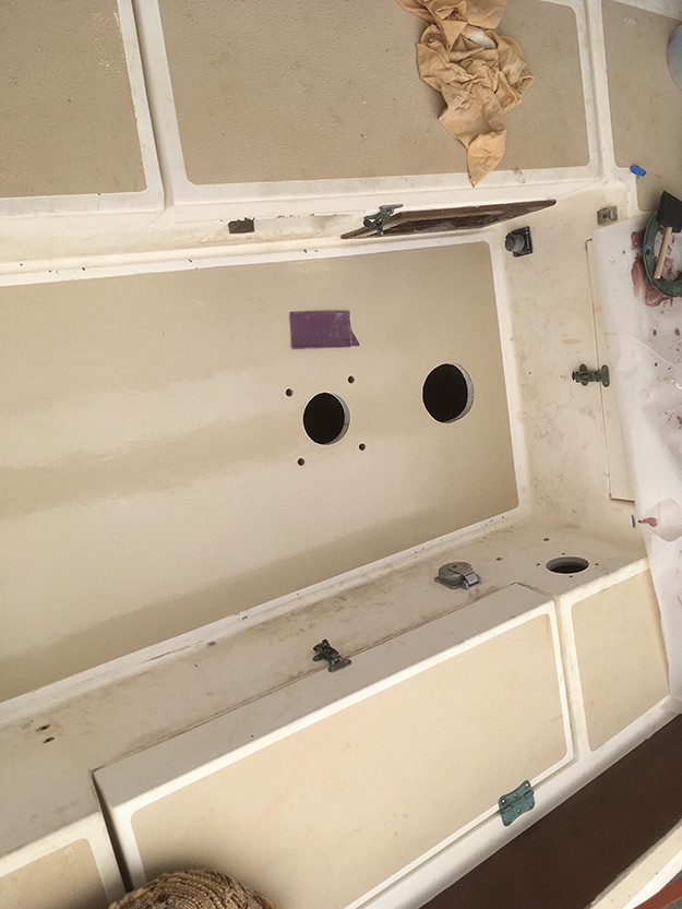
The cockpit sole was soft when I purchased Sanderling, but the side decks were solid. Soft side decks would have been a deal-breaker. But a cockpit sole is not too difficult to rebuild especially if you have already removed your rusty steering bracket to be rebuilt (see the Clunk post). I was certainly not going to install my new steering bracket under this cockpit sole and see it quickly destroyed by a leaking pedestal.
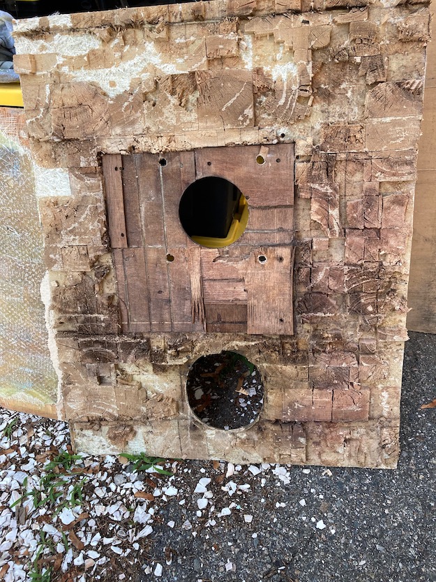
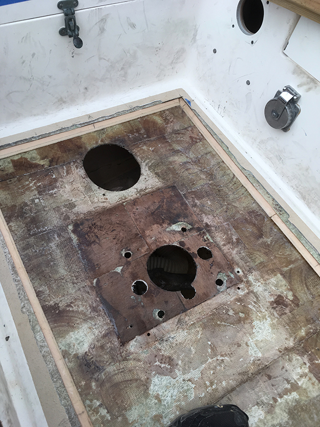
Sanderling had been on the hard covered for 7 years. I needed to determine how far the core rot had progressed. My tapping skills proved pretty good. I had estimated that from the aft end to about a foot before the bridge deck the core was punky. I did my cuts and removed the top layer. The plywood and balsa core around the pedestal was just dust, and the balsa towards the bridge deck was rotted and still holding water.
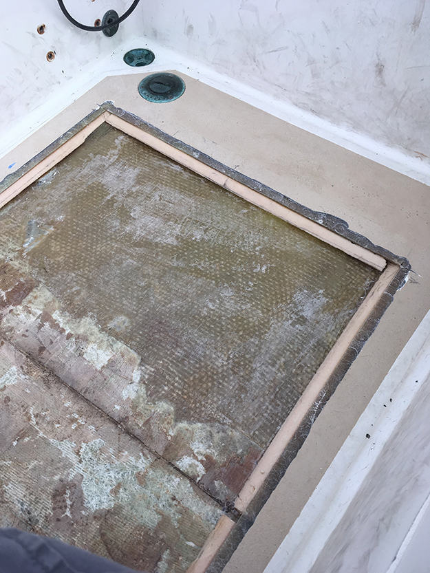
I used a simple circular saw and common blade to cut just enough depth to penetrate the top layer of glass over the core. I used a piece of square profile wood trim as a straight edge in between the saw and the locker side walls. Where the blade fell short of completing the cut in the corners (too cramped) I finished the cut with a cutting wheel. I got the top layer off in two pieces.
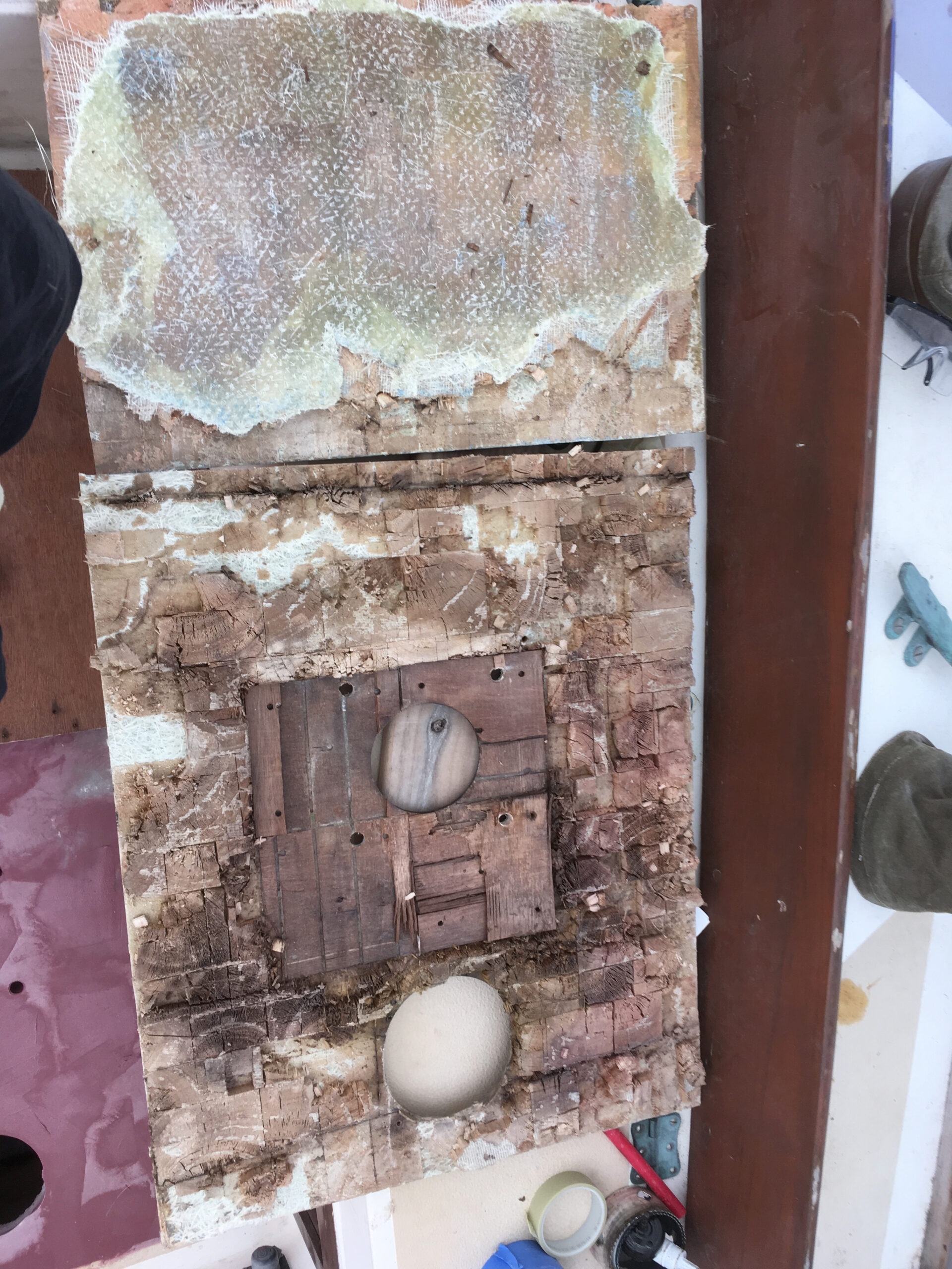
There was a seam of epoxy within the core about a foot from the bridge deck. So my tap guesstimate of the rot lined up with that. But water had made it beyond, that seam just made things sound solid while tapping from above. So I made a second cut removing the rest of that area of top layer. The balsa in that second piece was still adhered to the top layer, but as I pulled it up a thin layer of the moisture weakened bottom layer came up with it.
I chose not to re-use the top layer. It was tired and warped by water intrusion, with delamination at the pedestal bolt areas. The new sole would be synthetic core with layers of chopped strand and bi-axial glass.
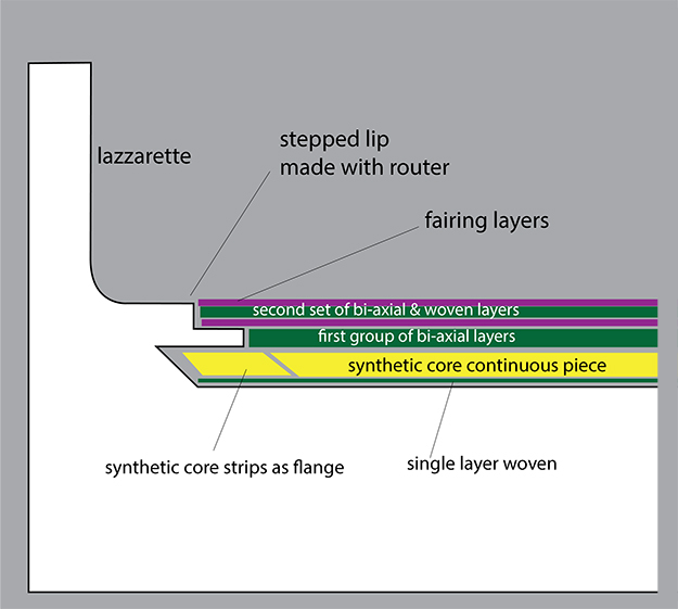
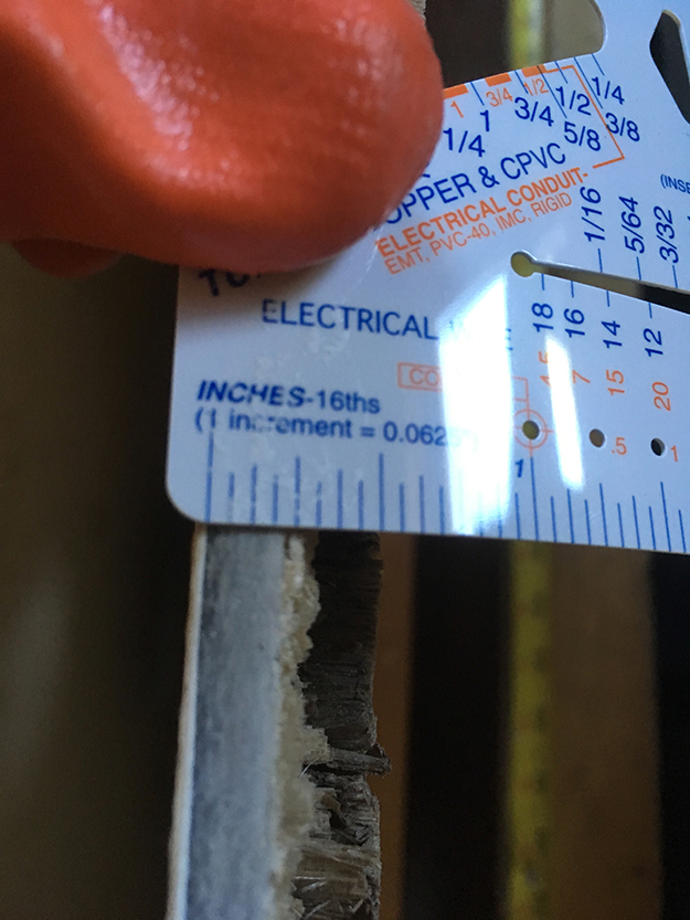
The original top layer of the cockpit was a full 1/4 inch thick. I had probably an 1/8 of an inch sag in the bottom layer from age, and the Divinycell (closed cell) core material was not as thick as the original balsa. So after the core was glued in first onto the bottom layer I’d need to build up almost one half inch of glass in order for the whole thing to be flush with the original sole. That worked out well as I’d rather have a very stiff and solid sole since it’s a high traffic area.
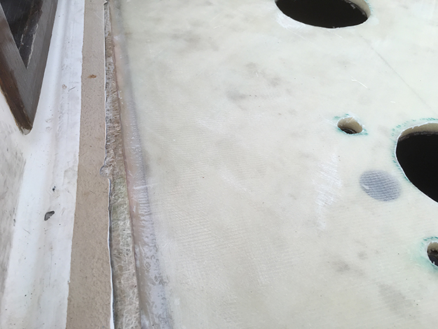
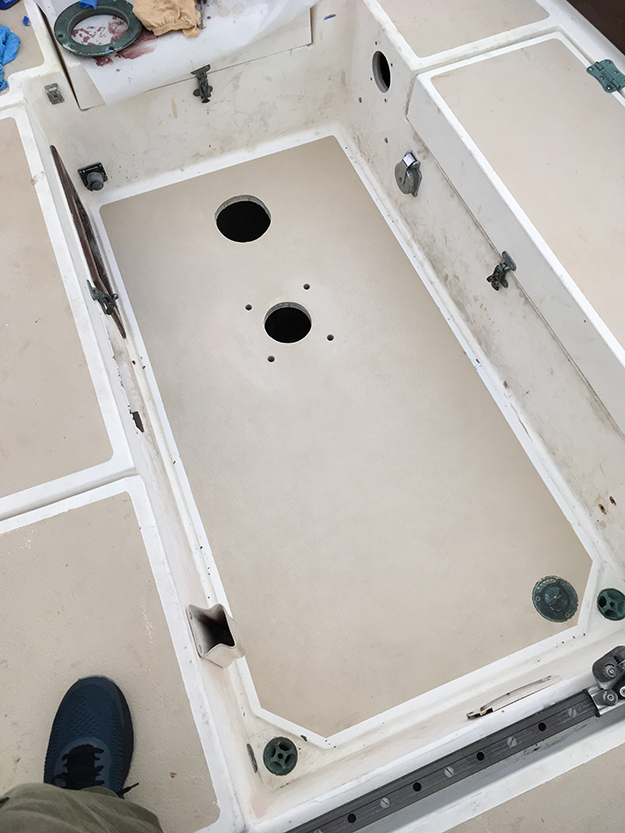
There was no way to cut an oversized continuous piece of core that would fit into the 1 1/2 inch edge cavity. And I did not want to leave it as a void. So I cut strips out of foam core with double taper and glued them in first using epoxy with filler.
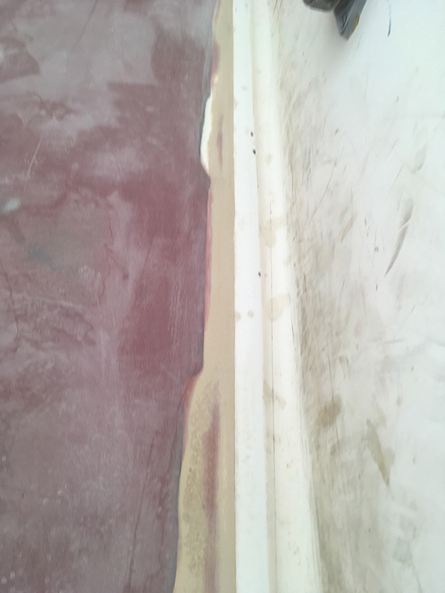
This would stiffen the edges and give the big piece of core a 45 bevel to sit on and glue to. You can see the step I made with the router. Not necessary to make the edge pretty since after epoxy, fairing compound, sanding and paint layers you won’t be able to tell anything happened.
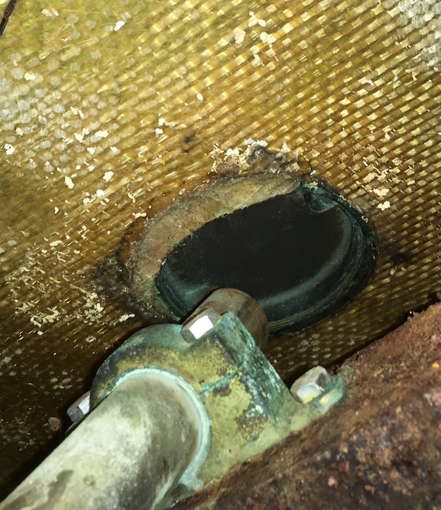
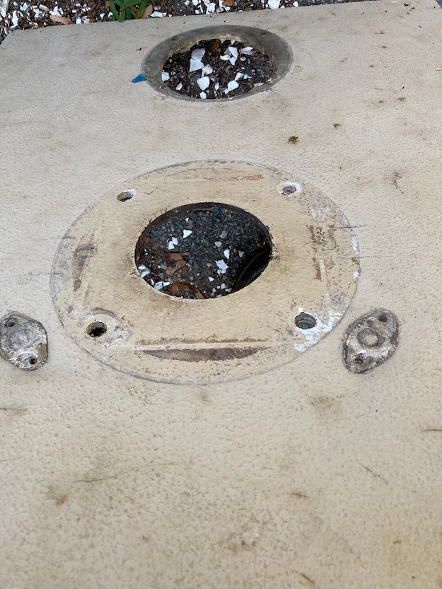
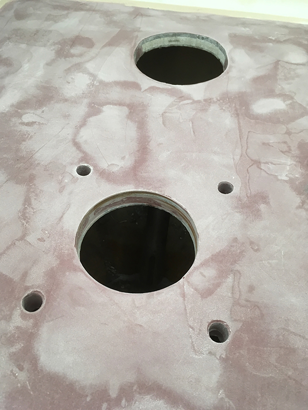
I also noticed from below that original builders had drilled out the hole for the emergency tiller in the wrong spot. Looked like they moved the hole back an inch and filled in the missing bit with a kind of crescent moon shaped plug. So when I glassed in the new sole top layer I was able to cut a fresh new hole out for the emergency tiller hatch in the correct spot. (tip – leave a bit of wiggle room with the hole and dry fit your emergency tiller hatch & tiller to ensure proper position)
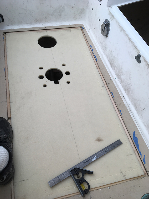
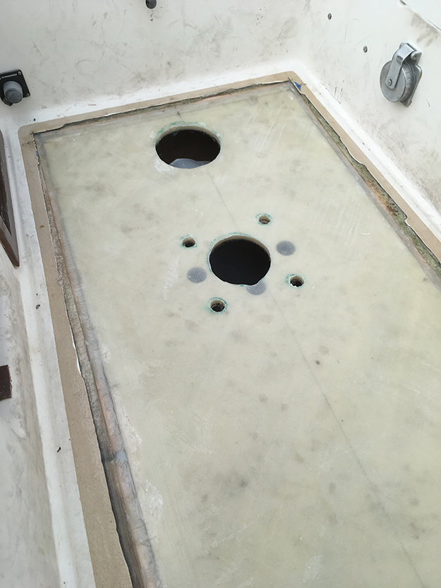
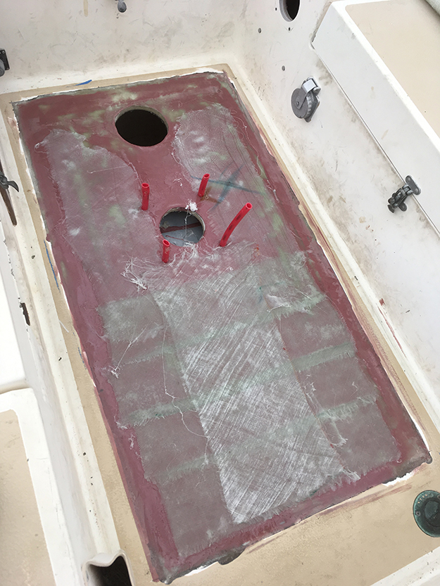
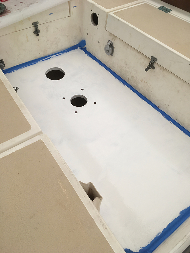
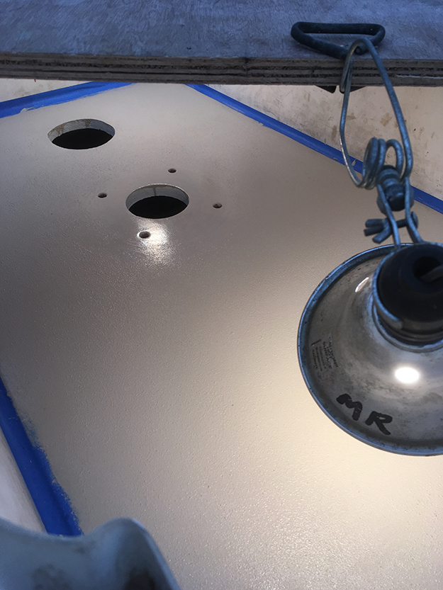
Bottom layer of cockpit sole wetted out with epoxy first. Single piece of foam core with reverse 45 bevel, sitting on the previously glued in 45 bevel edge strips. Weights applied to press core down while setting up. (tip-put plastic below to catch drips) The position of holes for the new core were marked from below by tracing the position of the existing bottom layer holes. The two extra holes seen here on either side are recessed cavities in the core for the heads of the bolts that hold the first two sheaves in place below (going through the steering bracket). The third extra hole serves the same purpose for the quadrant stop, also bolted in to the bracket below. The layers of glass just covered them up but when the steering bracket was installed it fit flush because those bolt-heads could tuck up into those recessed areas.
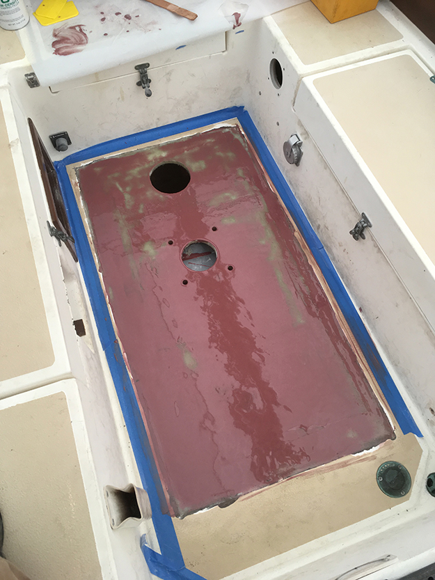
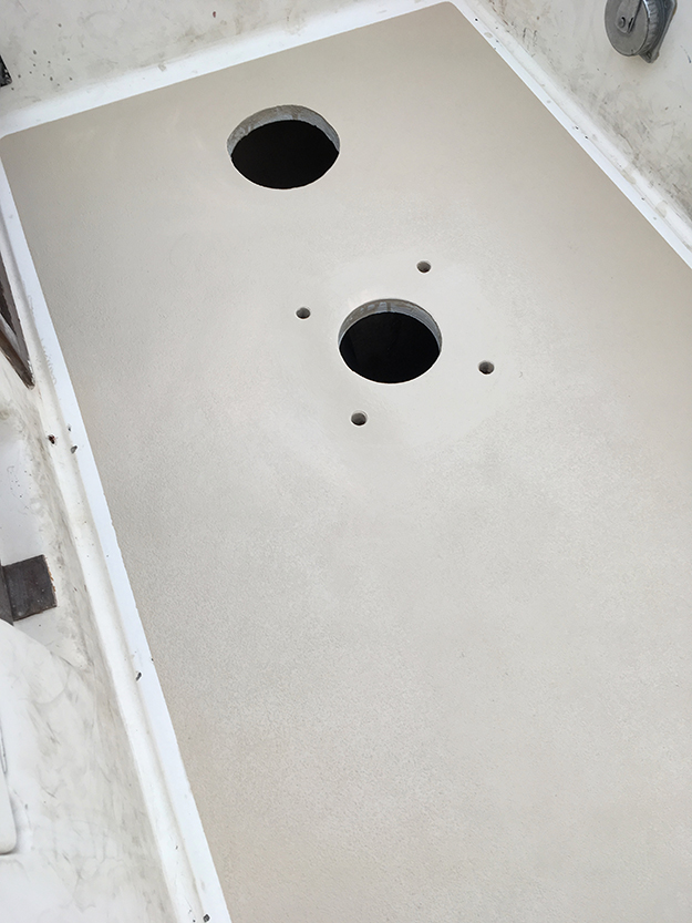
After routering out a 1/8 inch step in the edge of the top layer, I could put the first layer of bi-axial down and it would cover the core, the seam of the 45 bevel edge core I put in, and at least 1/4 inch of the original top glass layer (see illustration above)
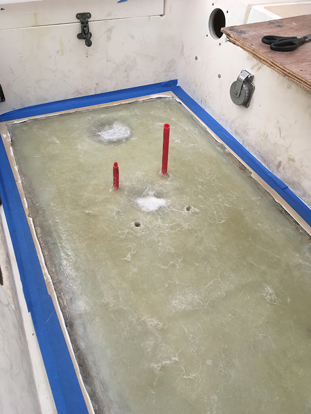
The larger holes were visible enough through each new layer that I could find their center and use a hole saw. But the pedestal bolt holes were hard to see. I didn’t want to have to drill out the holes from below. So I got some short pieces of 1/2 inch PEX and their actual OD was perfect for leaving room for the bolt and bedding. I just stuck them into the bottom layer pedestal bolt holes and built the glass up around them. This kept the holes exactly where they needed to be.
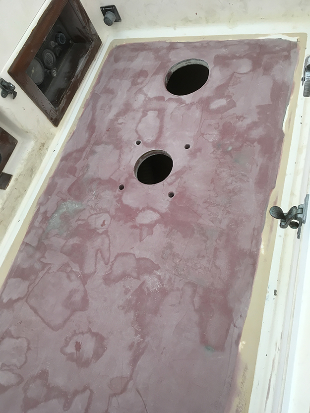
The bottom layer of the cockpit sole sloped a bit towards the bow, so as I built up layers the aft end was rising faster by an 1/8 of an inch or more. So I used fairing compound layers in between, and in the end had to use something bulkier, so I used up some remaining woven cloth. I built a squeegie out of a 2×4 and a piece of PVC trim that was the width of the cockpit, and used that to check the build-up, and to scrape the final fairing layer even with the edges.
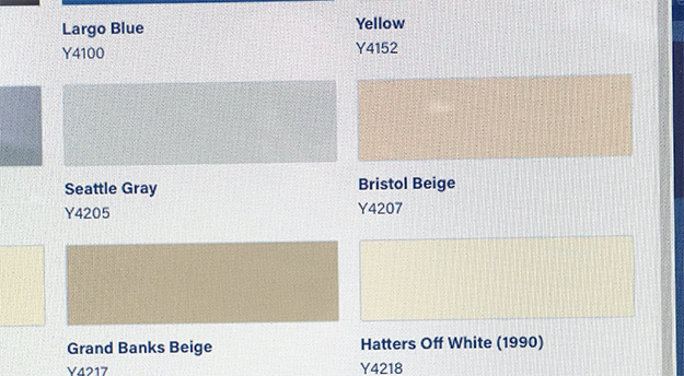
The color of my non-skids was somewhere in between the neutral look of Grand Banks Beige and the warmer look of Bristol Beige, so I bought a can of each and mixed them.
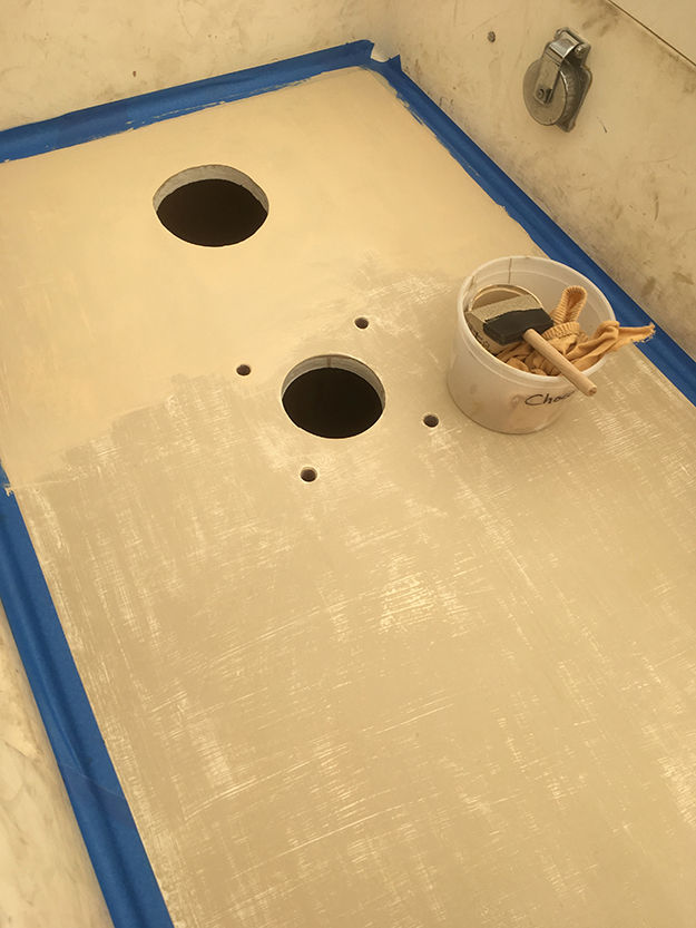
I actually lightly sanded my layers of broadcast non-skid after drying, because I did not want an abrasive surface that stood out against the worn nonskid on the rest of the boat. Then I switched to impregnating the paint with the nonskid and rolling on with a hard mottle roller, that worked great and helped move and evenly distribute the nonskid (the brush was no longer useful on a rough surface). I did two coats of paint over the two-part primer first, then build up about 3 or 4 more layers of paint and light nonskid. The results are much better than I expected, not having done any nonskid before. It looks good without making the rest of the worn out nonskid in other places look bad.